
RFID Product
Contact
Oversea Sales--joerica
E-mail: joerica@fonkan.com
Mob/Wechat: +8617603074791
Whatsapp:+8619874768776
Tel: +86-755-23202996
Add: Rm#308, No,213, Shajing Road, Shajing, Baoan District, Shenzhen, Guangdong, China
About Us
Current Location: > About Us
- Author: fonkan
- Source: fonkan
- Date: 2022-08-16
- Views: 1585Times
FDX-B frequency and modulation.
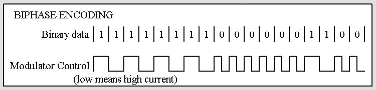
FDX-B protocol based transponders are defined to operate in the 134.2kHz band, and employ a biphase
encoding scheme to transmit their information. The data bit rate used is always fc/32.
Biphase encoding schemes modulate the RF field so that there is a transition at the beginning of each bit
boundary. A logic 0 state has a transition in the middle of the bit period, while a logic 1 state has no transition
during the entire bit period. For FDX-B 1 bit length corresponds to 32 cycles of the activated field of the reader.
FDX-B data structure.
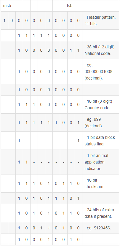
FDX-B protocol based transponders carry 128 bits of data. The structure of this data consists of:
11 header bits (10000000000) Lsb bit first.
64 identification bits with 8 control bits.
16 bits of CRC with 2 control bits.
24 bits of extended data with 3 control bits.
The control bits are simple logic 1 bits that appear after every 8 bits. They are used to differentiate the
11 bit header from the remaining data. Below is shown an example of the FDX-B data structure.
When the Tag enters the electromagnetic field transmitted by the RFID reader it draws power from the field
and will commence transmitting its data as shown above with the least significant bit (lsb) first. The 11 bit
header pattern is transmitted to indicate the beginning of the data block.
This is followed by 38 bits of the identification code. For an animal application this will be the identity code of
the animal. This is a unique 12 digit decimal code for each animal.
After every 8 bits is sent a logic 1 bit is inserted to differentiate data from the header sequence.
This is followed by the 10 bit country code. A country code is a 3 decimal digit value used to refer to
individual manufacturers. A code of 999 is used to indicate that the transponder is a test transponder and
need not contain a unique identification number.
The 1 bit data block status is an indicator flag to indicate whether an additional data block exists. A value of 1
indicates that the transponder contains an additional 24 bit data block. Otherwise it is 0. Following this we
have 14 reserved bits allocated for future use.
The animal application indicator is a single bit indicating that the transponder is used for animal identification.
This value is set to 1 to indicate an animal identification application, and 0 otherwise.
The preceding 64 bit block (excluding control bits) is then used to calculate a 16 bit checksum. The calculation
for this CRC checksum is defined in ISO 11784 & 11785 and is included after the animal status bit.
After the CRC check bits we have the extra data block. This data block exists if the data block status flag is 1.
When the data block status flag is 0 this value will be 000000. The data block may be used to append
additional data relevant to the individual application.
Priority 1 Design carries a stock of low cost rfid reader writer units that are capable of reading and writing
FDX-B and HDX protocol transponders.
FDX-B protocol based transponders are defined to operate in the 134.2kHz band, and employ a biphase
encoding scheme to transmit their information. The data bit rate used is always fc/32.
Biphase encoding schemes modulate the RF field so that there is a transition at the beginning of each bit
boundary. A logic 0 state has a transition in the middle of the bit period, while a logic 1 state has no transition
during the entire bit period. For FDX-B 1 bit length corresponds to 32 cycles of the activated field of the reader.
FDX-B data structure.
FDX-B protocol based transponders carry 128 bits of data. The structure of this data consists of:
11 header bits (10000000000) Lsb bit first.
64 identification bits with 8 control bits.
16 bits of CRC with 2 control bits.
24 bits of extended data with 3 control bits.
The control bits are simple logic 1 bits that appear after every 8 bits. They are used to differentiate the
11 bit header from the remaining data. Below is shown an example of the FDX-B data structure.
When the Tag enters the electromagnetic field transmitted by the RFID reader it draws power from the field
and will commence transmitting its data as shown above with the least significant bit (lsb) first. The 11 bit
header pattern is transmitted to indicate the beginning of the data block.
This is followed by 38 bits of the identification code. For an animal application this will be the identity code of
the animal. This is a unique 12 digit decimal code for each animal.
After every 8 bits is sent a logic 1 bit is inserted to differentiate data from the header sequence.
This is followed by the 10 bit country code. A country code is a 3 decimal digit value used to refer to
individual manufacturers. A code of 999 is used to indicate that the transponder is a test transponder and
need not contain a unique identification number.
The 1 bit data block status is an indicator flag to indicate whether an additional data block exists. A value of 1
indicates that the transponder contains an additional 24 bit data block. Otherwise it is 0. Following this we
have 14 reserved bits allocated for future use.
The animal application indicator is a single bit indicating that the transponder is used for animal identification.
This value is set to 1 to indicate an animal identification application, and 0 otherwise.
The preceding 64 bit block (excluding control bits) is then used to calculate a 16 bit checksum. The calculation
for this CRC checksum is defined in ISO 11784 & 11785 and is included after the animal status bit.
After the CRC check bits we have the extra data block. This data block exists if the data block status flag is 1.
When the data block status flag is 0 this value will be 000000. The data block may be used to append
additional data relevant to the individual application.
Priority 1 Design carries a stock of low cost rfid reader writer units that are capable of reading and writing
FDX-B and HDX protocol transponders.
Copyright © Shenzhen Fonkan Technology Co.,Ltd.
URL: www.fonkan.com E-mail: joerica@fonkan.com ICP:粤ICP备17081219号-1
URL: www.fonkan.com E-mail: joerica@fonkan.com ICP:粤ICP备17081219号-1